Shot Notes
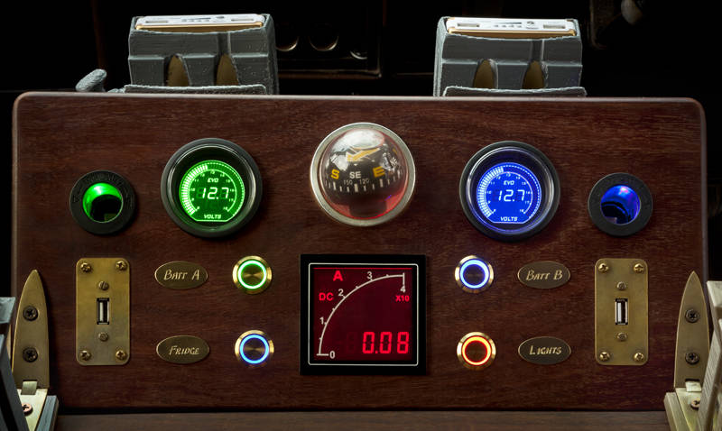
This is the third generation power control board in our van. The first and second design worked but I have tried to simplify the controls. I am a novice when it comes to electronics however building these boards have been essential to photography on the road, as camera batteries and laptops always need charging. Unfortunately, I may have oversimplified it as switching on either battery now appears to connect both batteries together via the amp meter. I am not sure if there is an alternative button wiring or a fix with diodes, and if so which type of diodes? Any suggestions?
Update: The Mark Four
Wow!
Send schematic for review.
Schematics in my head at the moment. I’ll try to sketch something out.
After further testing it only connects the batteries together if you turn on both sides. I wanted to keep left and right channel separate so you can check both voltages at the same time.
What are 51,52 and 53? The Ammeter should have effectively zero resistance so if the four wires going in at the top would normally go to ground if there were no meter this circuit is close to perfect. If the meter has appreciable resistance then there will be some cross current flow.
S1, S2 & S3 are the switches. Will these diodes stop the cross current flow?
I am a little confused as all the switches have three wires and I don’t see the PV. Am I right in thinking you basically want to monitor the state (V) of each battery and select which battery gets the sunlight? Are you interested in charging current or discharge current as the meter is not centre zero it can’t do both?
The switches have +12V, ground & output which is also wired their indicator light. They also have an unused inverse output which may be useful. I spoke to Photonic Universe about their solar controller. It can handle the alternator but must not have the batteries detached once the PV is connected. So both batteries and the PV are permanently attached their controller. My circuit just deals with output loads now.
OK then just feed your circuit with a diode between each battery and your circuit. You will only lose about 200mV with a Schotkey diode. Good luck.
Thanks, I will order these diodes then.
They look beefy enough, 12A.
Diodes installed, It’s now working as planned.
[…] Blue Mountains until the Australian federal election on 18th May. While I am here I am upgrading power control board in my van and uploading to stock […]
[…] boards, which each stage has used, were intended to be easy to replace. The first, second and third designs all worked but after using them for a while I decided to removed features I did not use and […]